Category Archives: This Old Comanche

The Fuel Pressure Problem

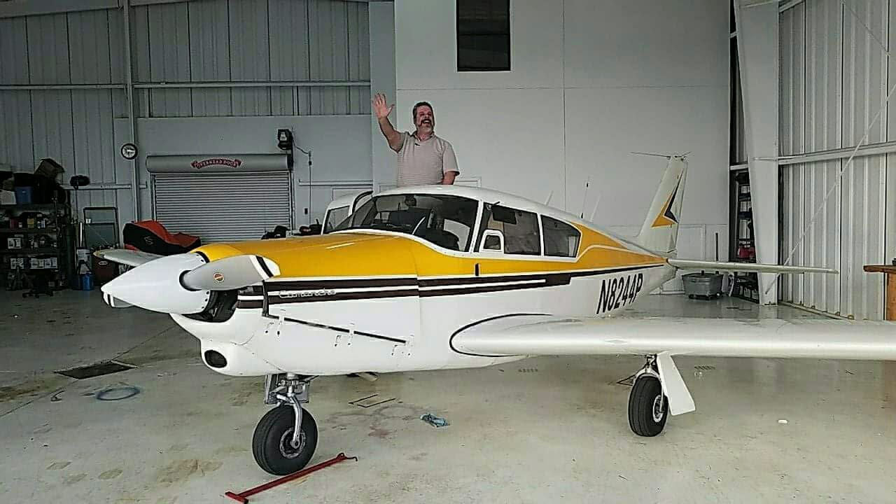
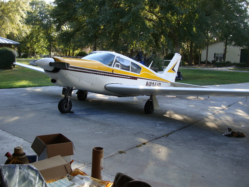
Had a little issue today with Sunny Side Up. I was taking a short flight to go see an old friend and mentor. On climb out, at 1000 feet I shut off the boost pump and fuel pressure went from near the top of the green almost to zero, right at the bottom of the green zone. This is different from normal as it usually stays about in the middle of the green.
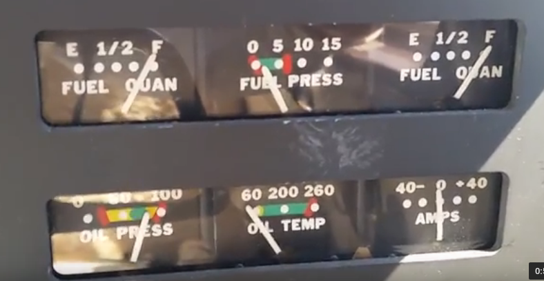
Low Fuel Pressure

Low Fuel Pressure

The Engine continued to run fine. I turned the pump back on and the pressure went back up to the middle of the green. Once I leveled out at 4k I turned off the boost pump and the needle went to about the middle of the green. I will admit some panic set in as I worked the problem.  I’m glad it was a clear day with no clouds and great visibility.  I could not imagine how I would have reacted had I been inside a cloud.

I continued the twenty minutes or so of my flight. As I neared my destination and began my  descent, as part of normal landing procedure, I turned the boost pump back on and the pressure went above the green zone. I now had an over pressure situation.  Curiouser and curiouser.

My friend and mentor suggested it might be the check valve in my electric boost pump is stuck open. Another thought was that the engine driver mechanical pump, new at overhaul, about 350 hours ago, was failing.  I hoped that was not the case as replacing the pump is no small task.

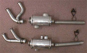
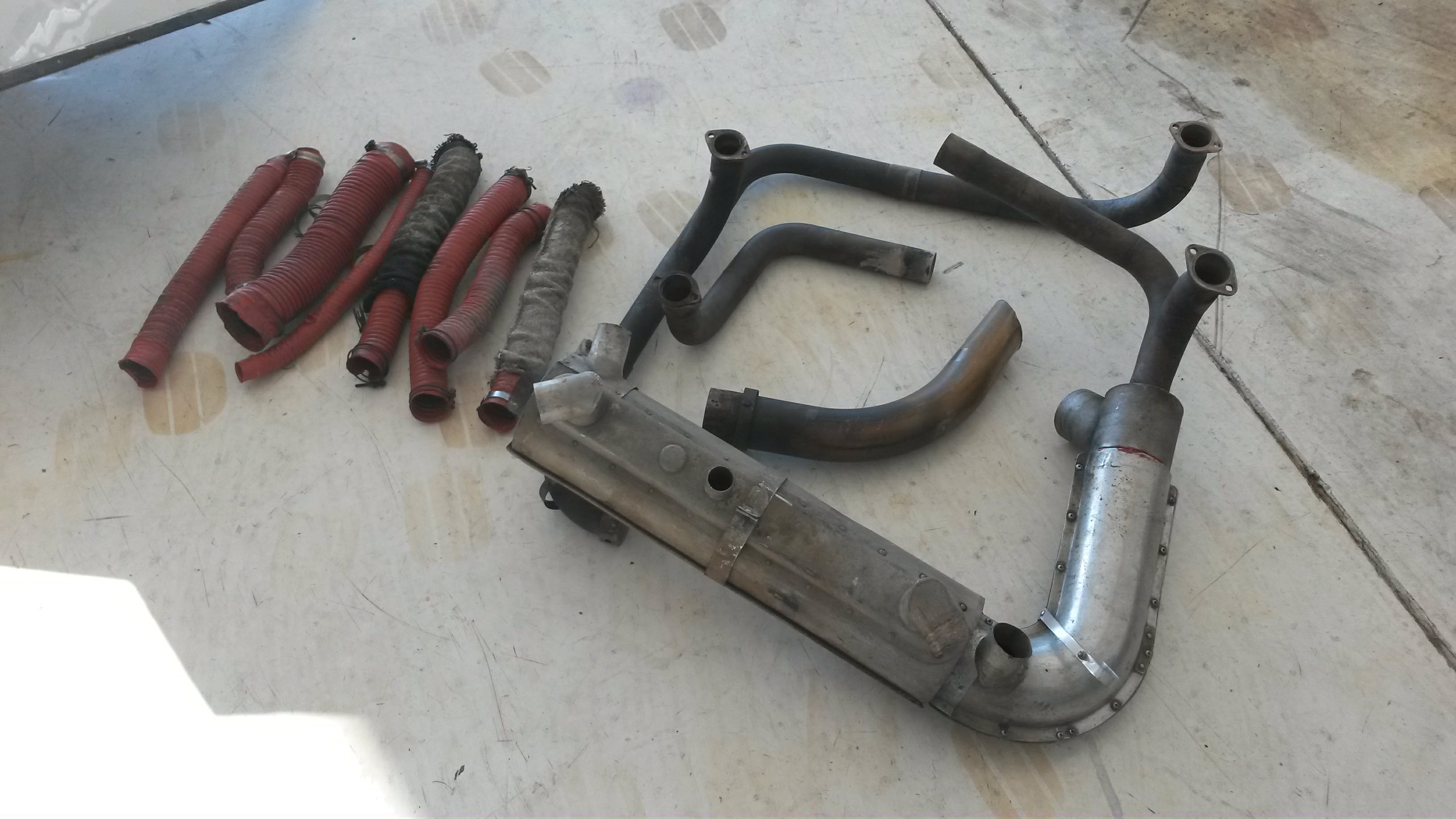
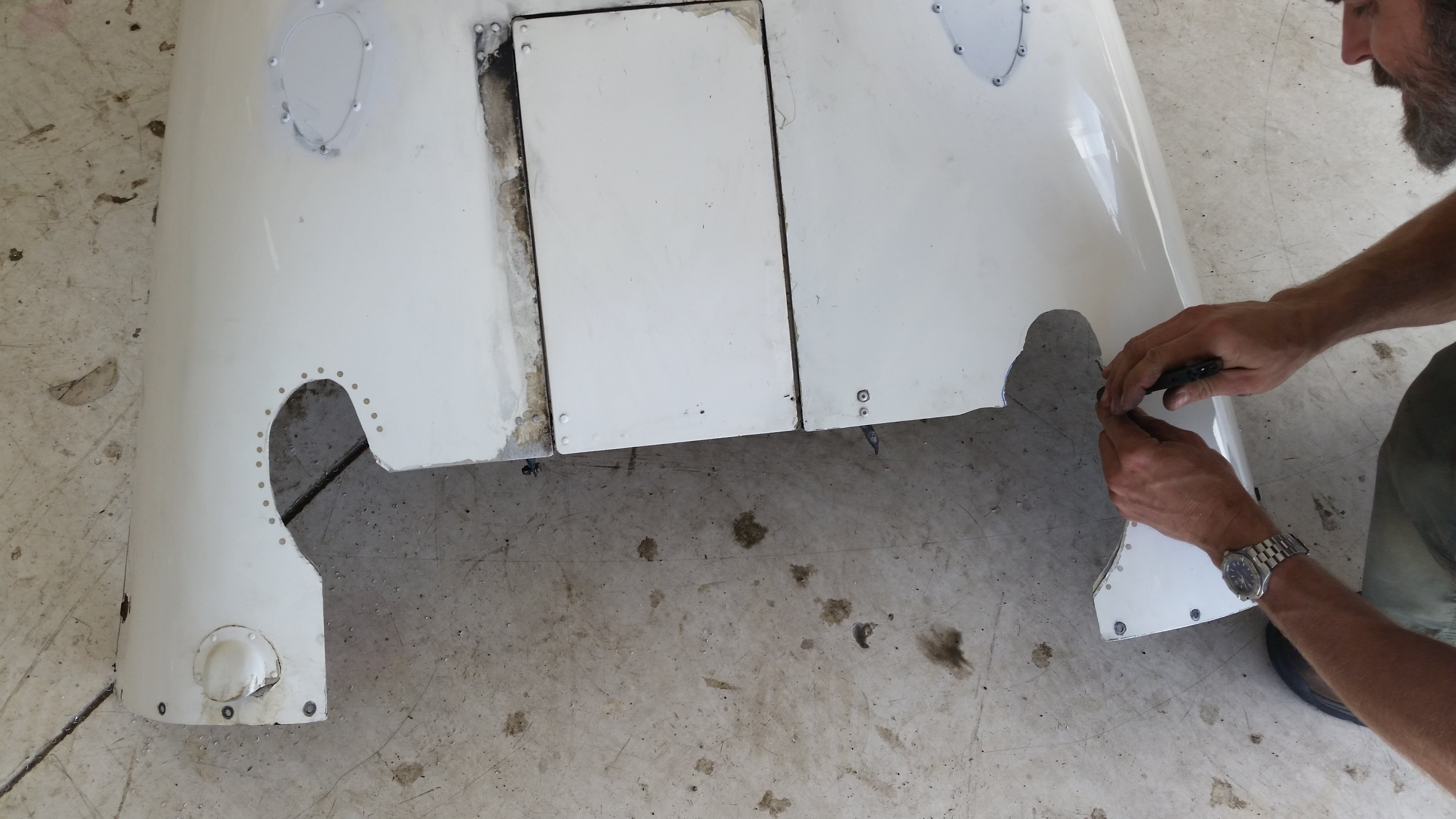
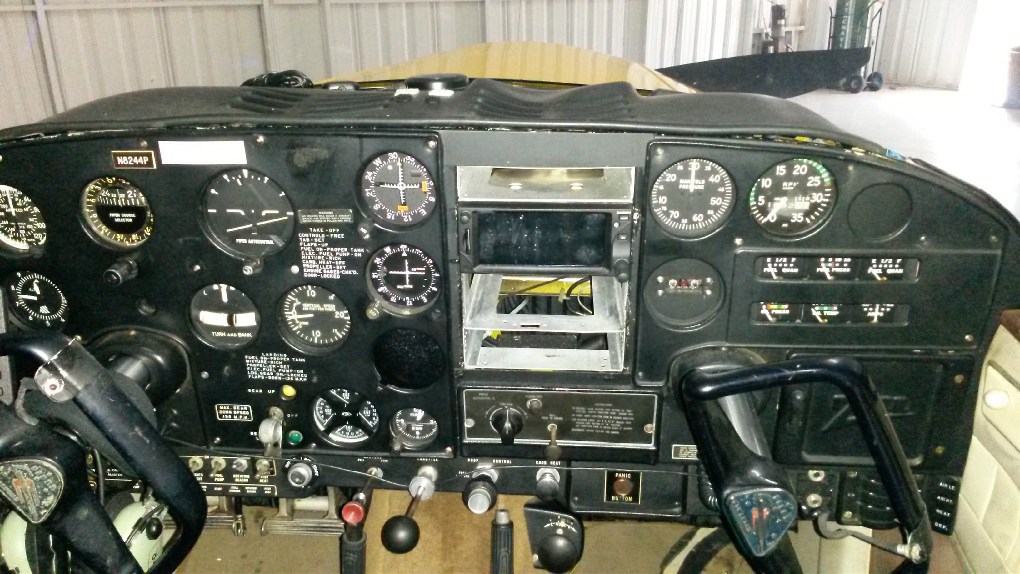
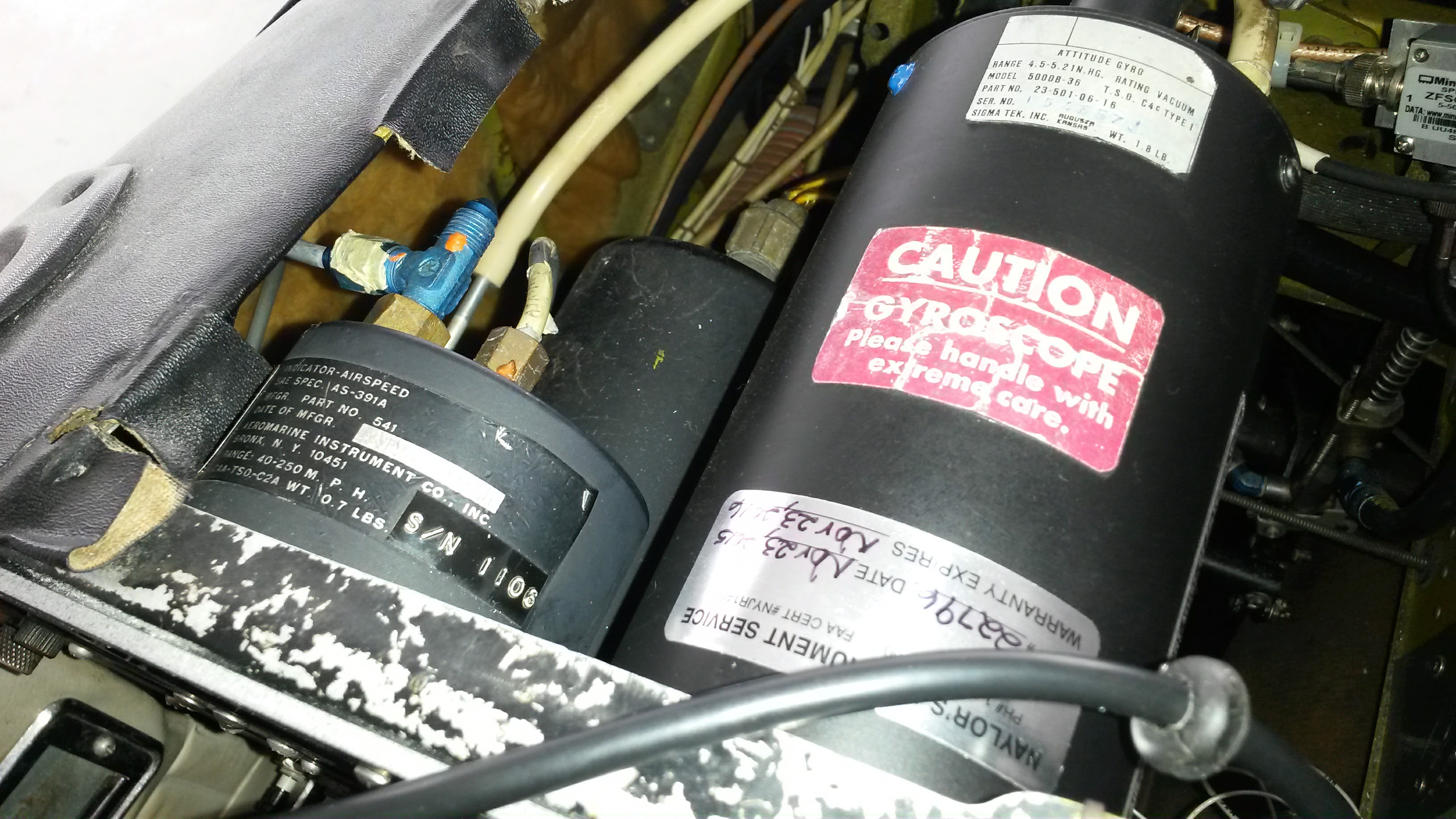
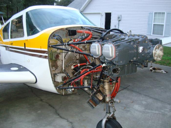
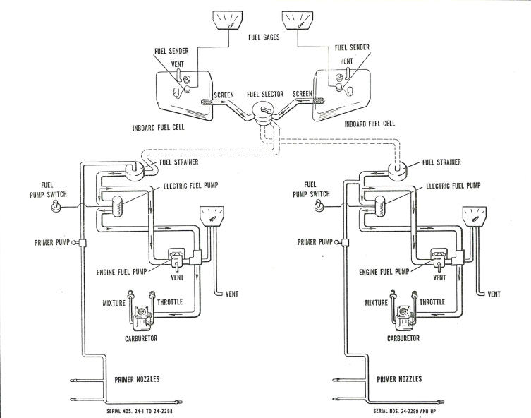
The Comanche fuel system is not all that complicated.  Two tanks come to a fuel selector and then fuel is fed through a strainer to an electric and engine driven pump, which both feed the carburetor.  In the picture below mine is the one on the right.

Piper Comanche Fuel System

Air Inside the Lines

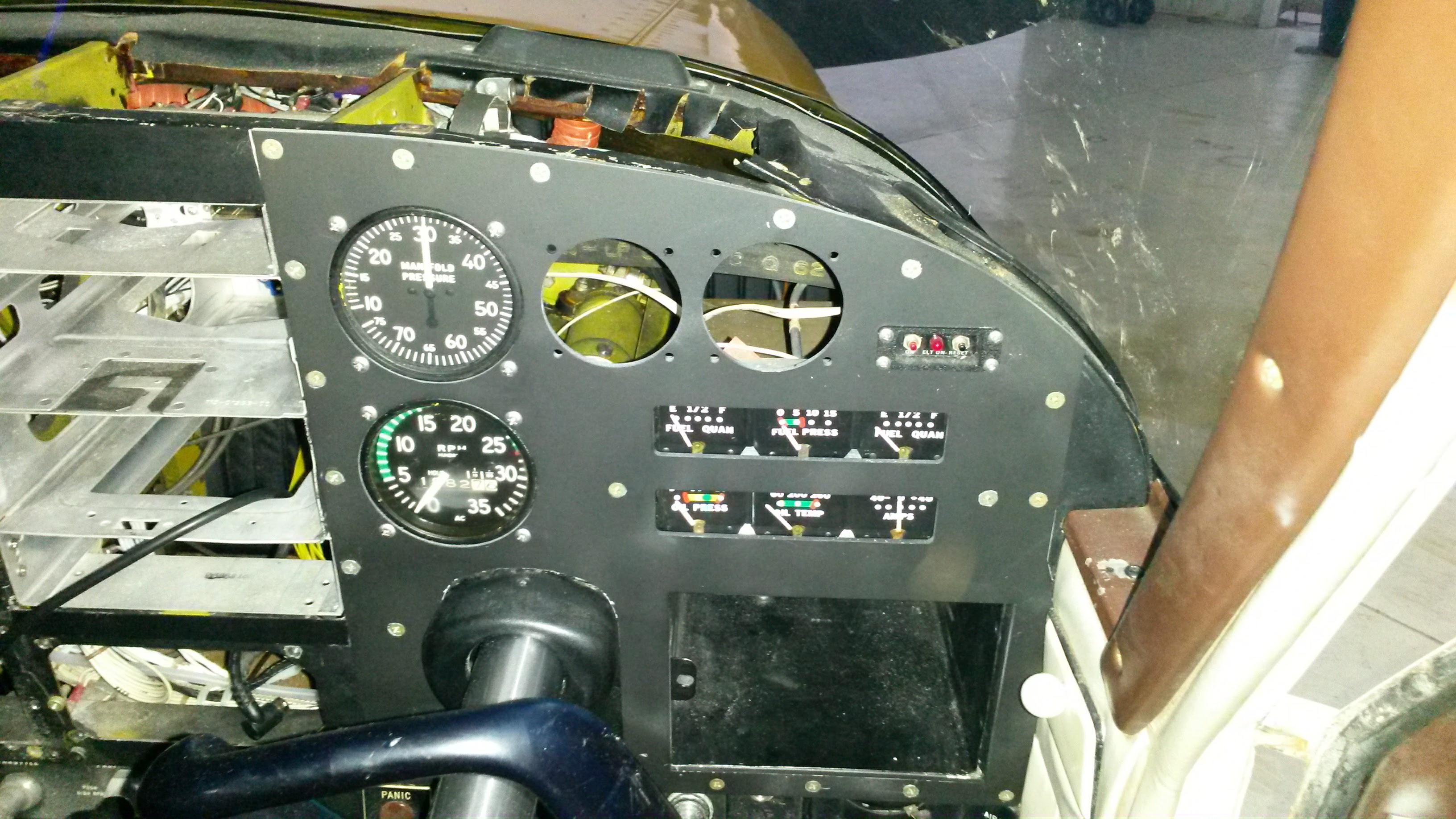
I had some discussions with experts and mechanics alike in order to help diagnose the problem.  First off the manual states that the pressure “should not be under 0.5 pounds nor over 6 pounds, with a desired pressure of 3 pounds”  Based on the gauge, my fuel pressure was awfully close to that lower number.  But, was my gauge even accurate?  It is fifty eight years old.

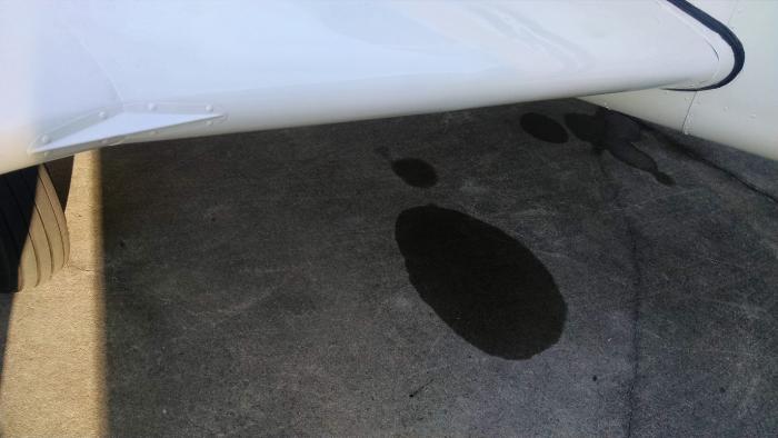
Some of the clues to the problem came from that under and over pressure situation.  The fact that the fuel pressure went up upon descent meant that there was air inside the lines, which expanded once at a lower altitude where air pressure is higher and causes expansion.   Another clue was that the pressure gauge would fluctuate rapidly when the engine was at idle.  That is called cavitating and it clued us in that air was somehow entering the fuel lines.  Another clue was that the primer was dry.  That is to say, the primer had to be pumped to pull fuel back up to it.  So it was not staying loaded as it should, but the fuel was seeping back down the line.  Lastly and most perplexing was the lack of fuel staining or smell anywhere in the cabin or engine compartment.  if it was leaking, it was very small indeed.


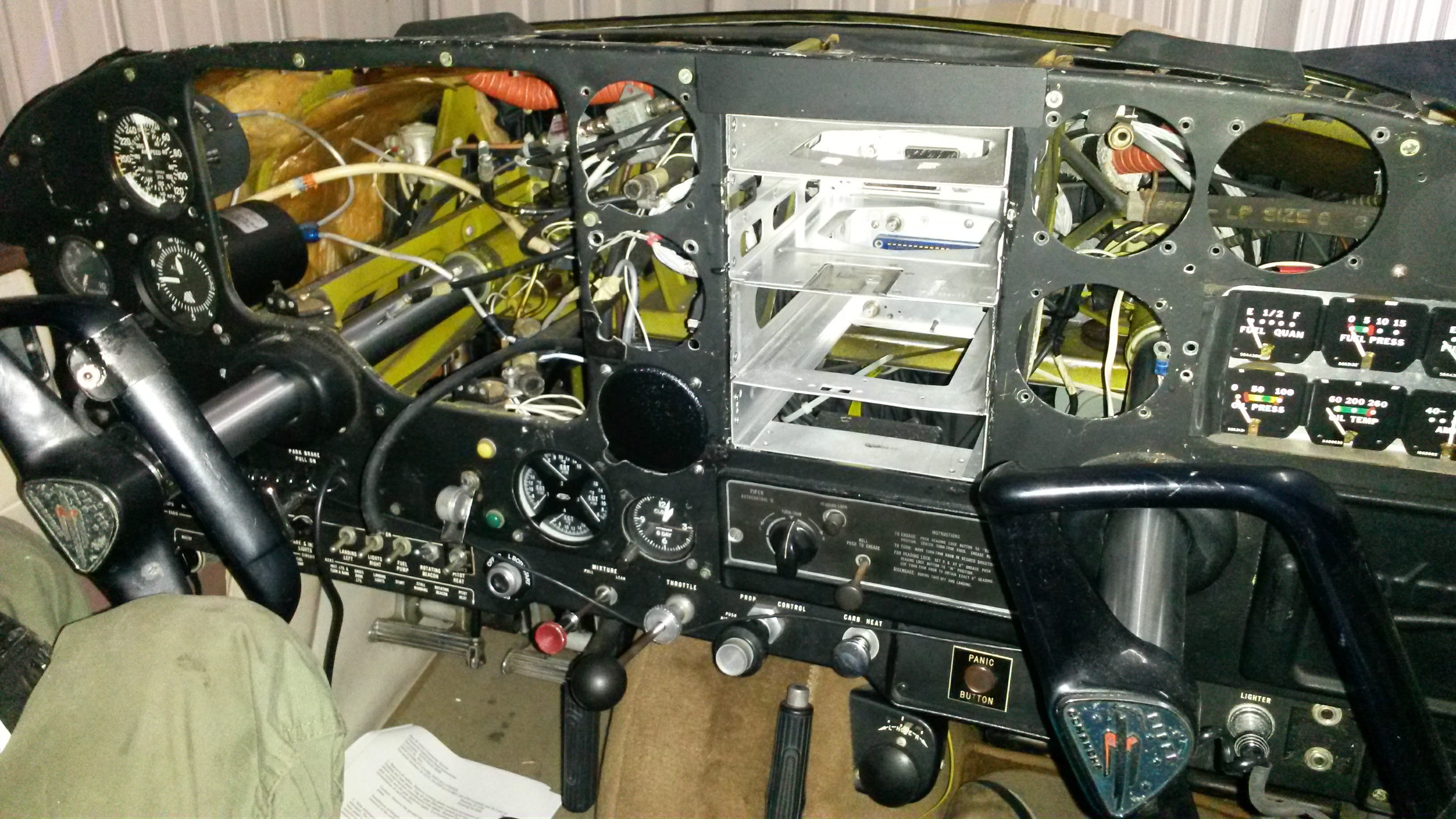
How To Find an Air Leak

Based on the fuel system of the Comanche, air could be entering the system at several places. The fuel tank selector, the primer handle, either of the pumps, and the fuel lines themselves.   SO many places to look made the whole situation overwhelming.  It was hard to pick a starting point.  The mechanic and I settled on the primer problem first.

If the leak was in the primer or attached lines, I would have a hot cylinder as this would possibly create a lean condition in one of the cylinders.   Come to think of it, Number 1 cylinder was hotter than the rest.  So yet another clue.

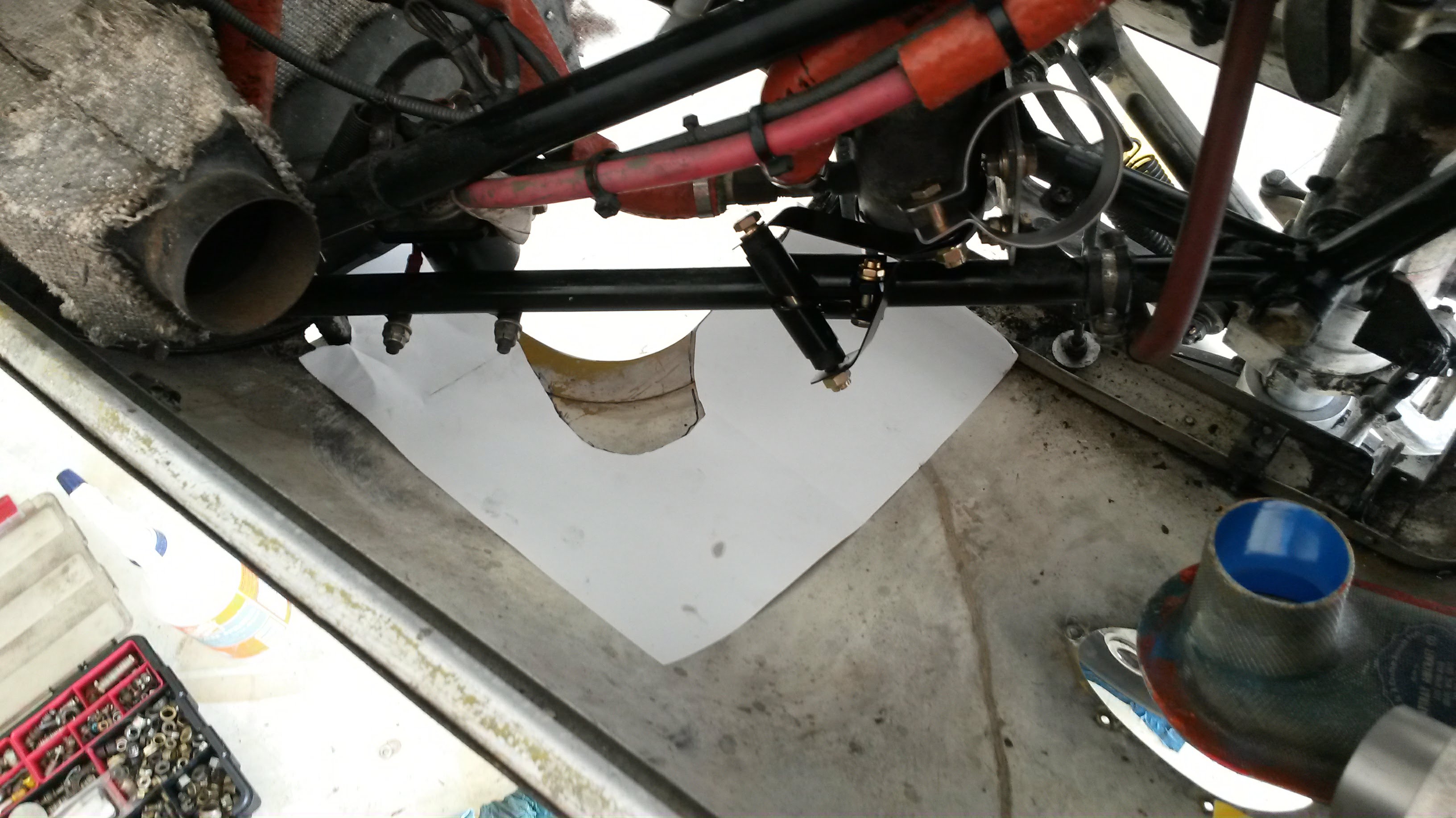
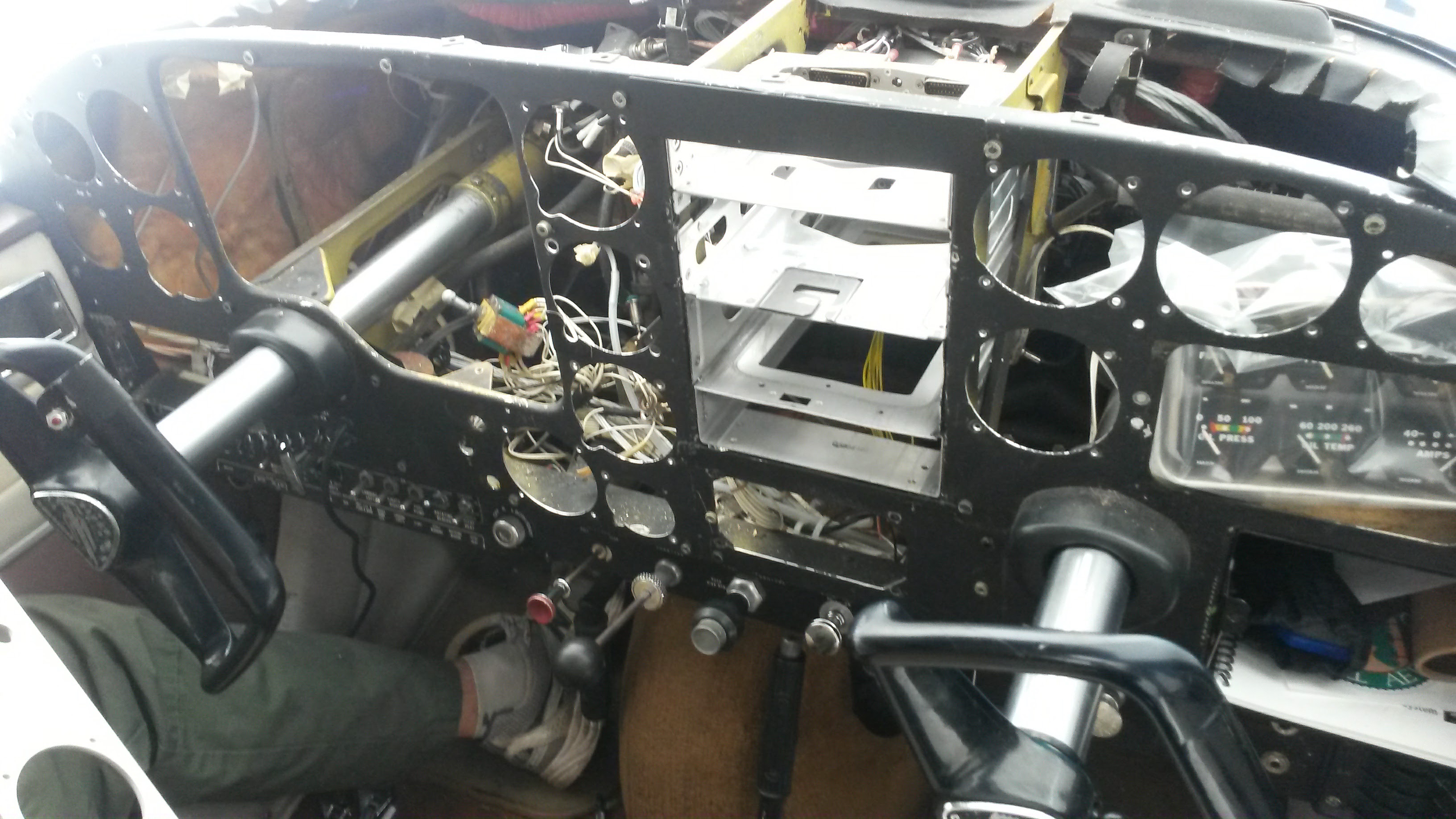
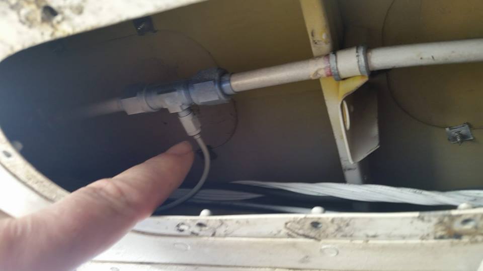
The first test was to pressurize the primer system. air was forced through the primer lines just before the primer and lo and behold we found a small leak where the primer line attaches to the main feed under the plane.   This was a simple fix.  Loosen the connections and then re-seat and tighten them.  The leak stopped.  I hoped that the problem was fixed, but no not yet.  The fuel pressure was still really low.

My mechanic then stood staring at the engine for a while whilst rubbing his chin.  A classic “Don’t bother me I am thinking” pose I often see.   He then went and got a spray bottle of soapy water.  He had me lock the brakes and put a chock on the front wheel.  He instructed me to start the engine and put it at idle.   He then walked up behind the prop and opened the cowling.  This part always makes me nervous.

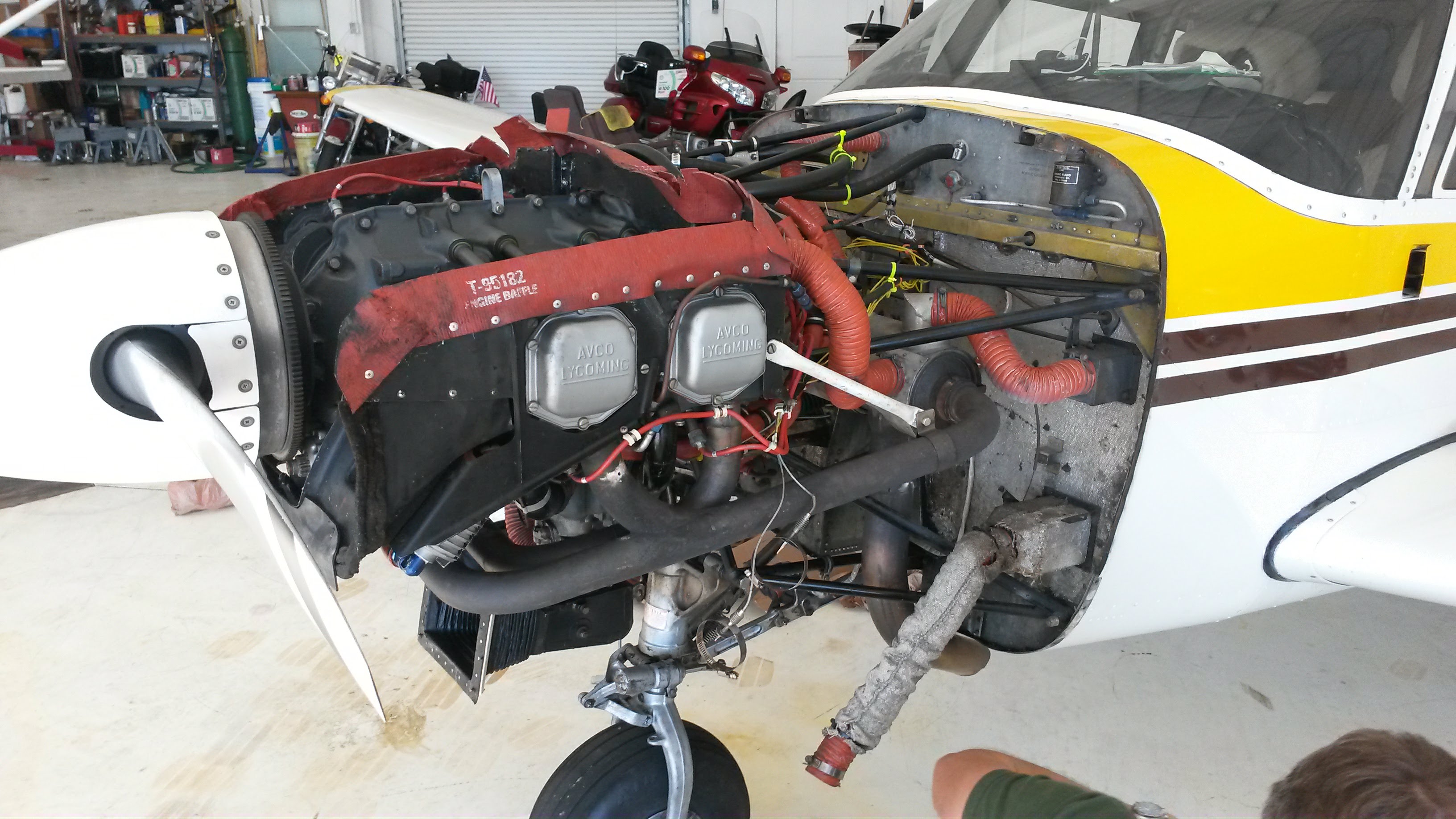
He would spray and then look up at me an ask it there was a change in the fuel pressure reading.  He sprayed cylinder 3 intake pipe and something did happen.  The engine stumbled and the pressure fluctuated wildly. The intake on number 3 cylinder was sucking air.   My mechanic had a wide grin on his face.   The soapy water bubbled for just a moment before being sucked into the intake and making the engine stumble.  But why did the fuel pressure fluctuate?

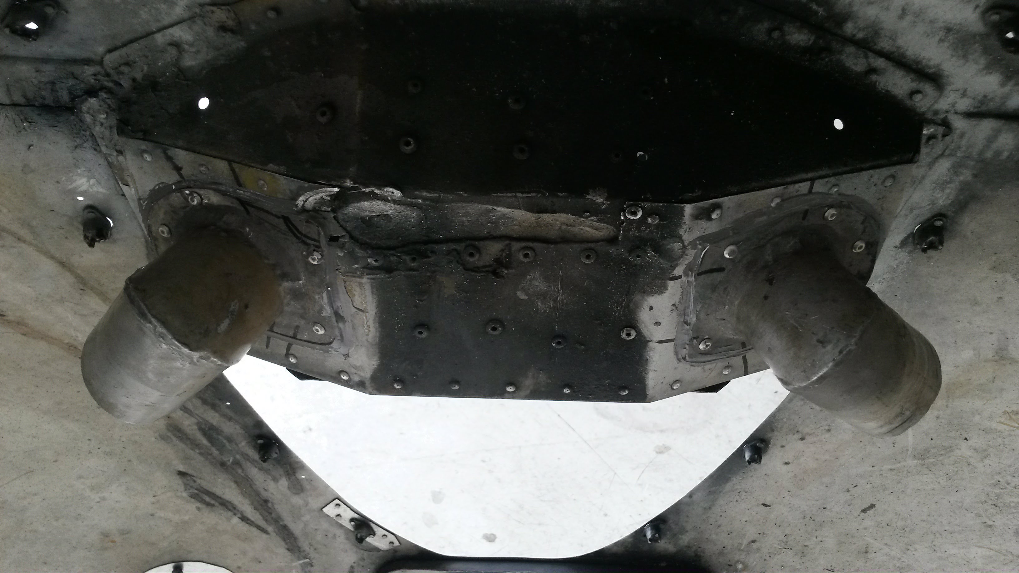
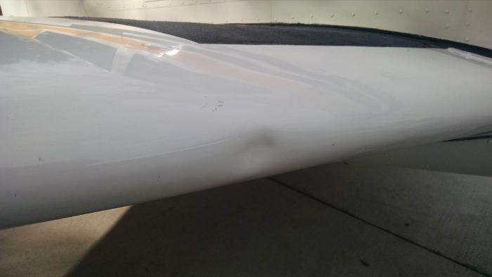
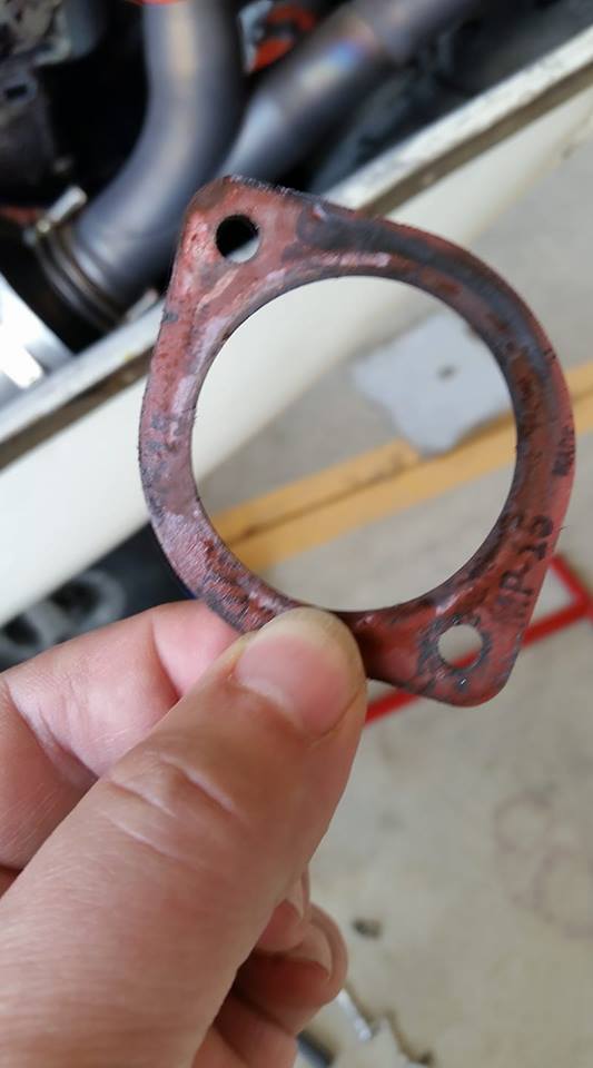
A removal of the intake pipe revealed that the gasket had failed.  From the picture it is easy to see the back soot where the air was seeping past the gasket and being sucked into the cylinder and causing a lean condition and extra heat.  Fifteen minutes, a new gasket and re-torquing the bolts solved this issue.

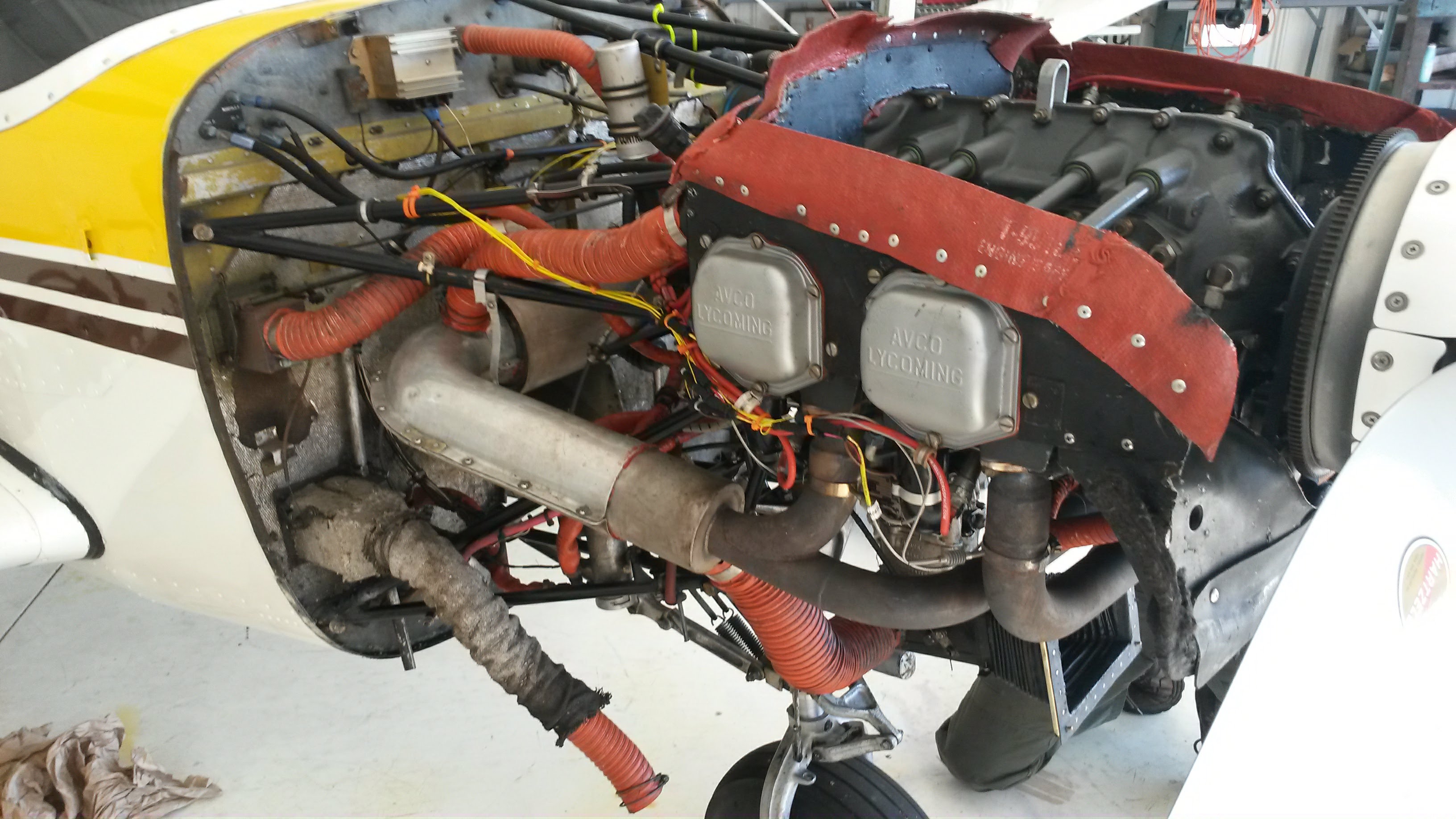
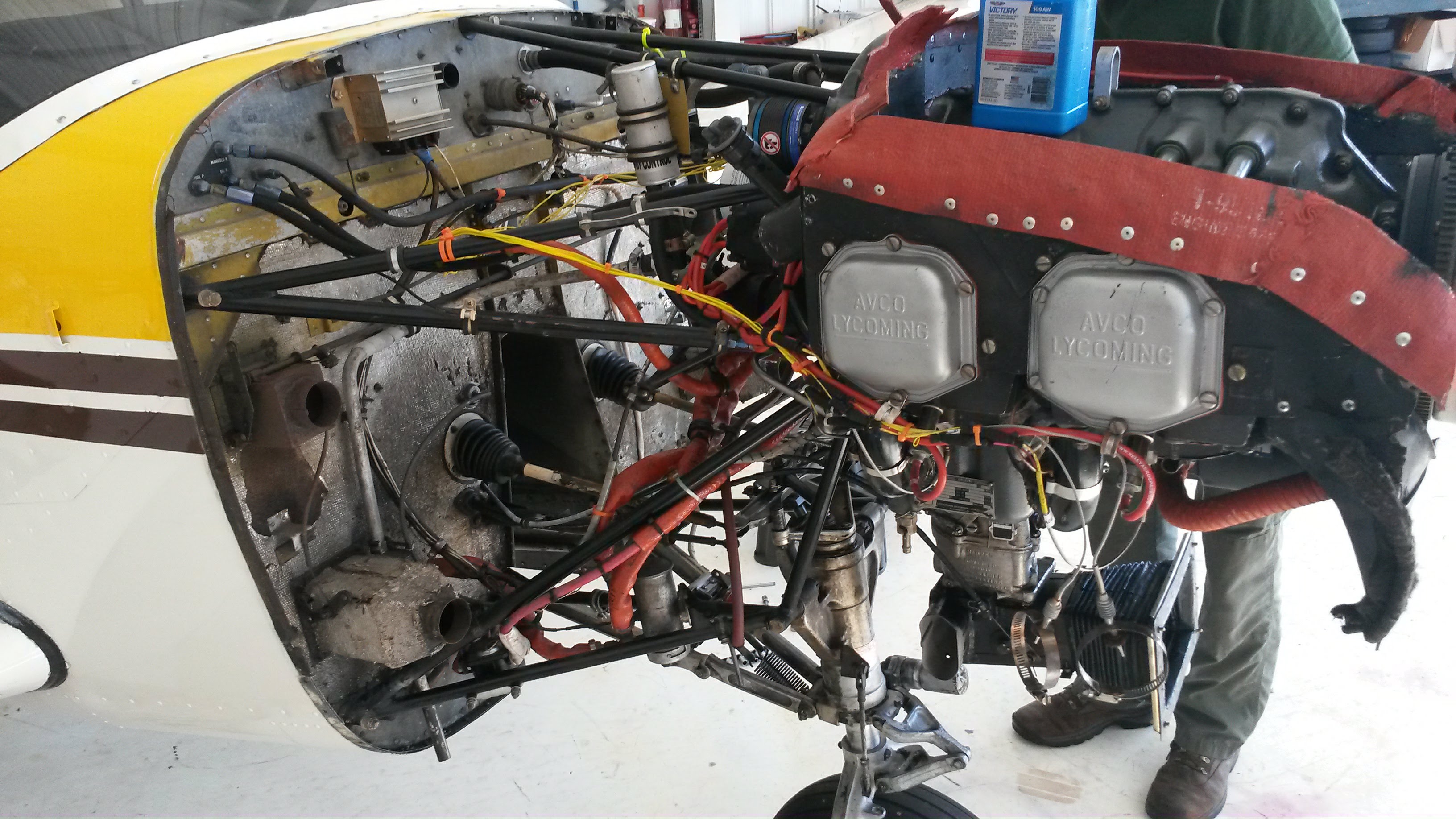
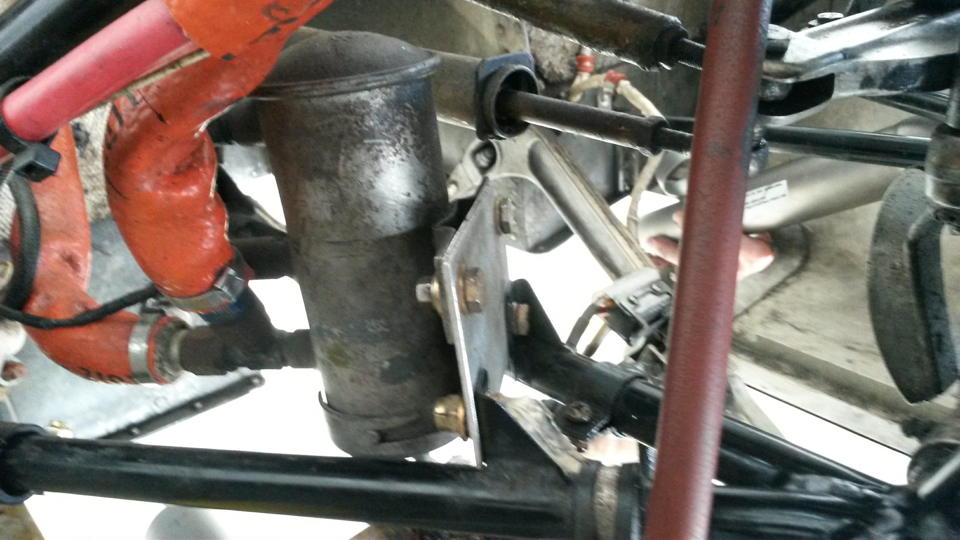
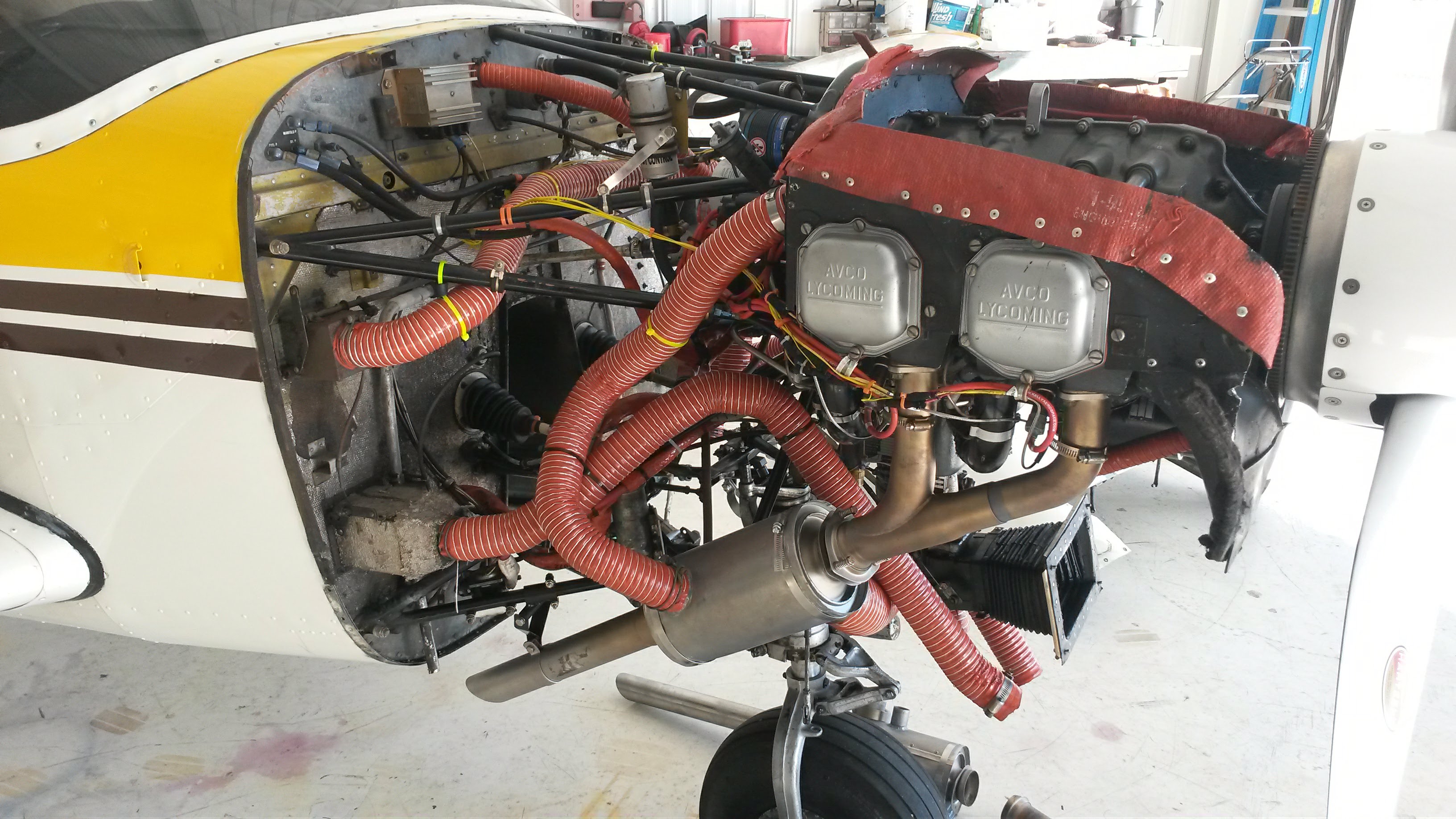
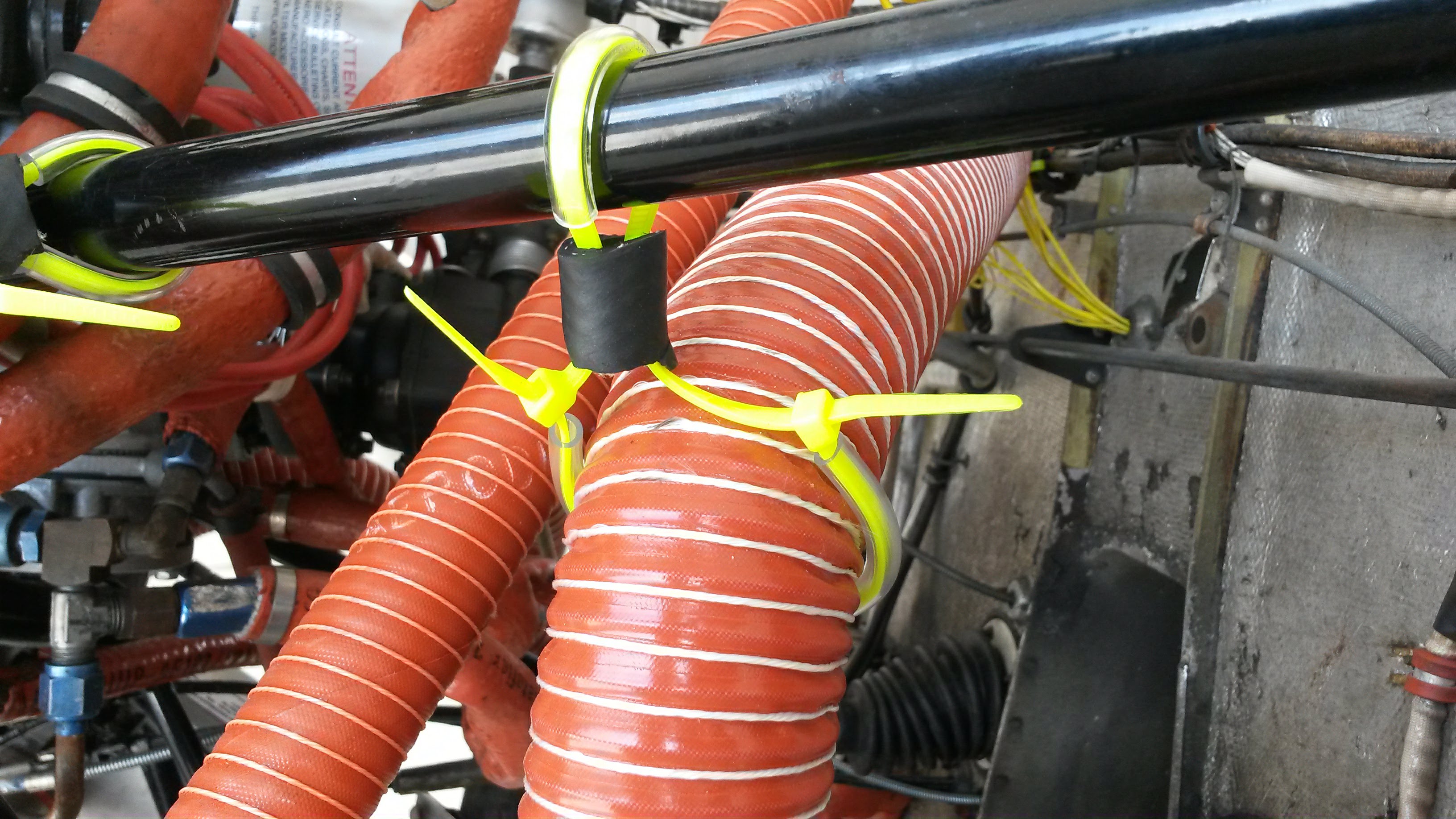
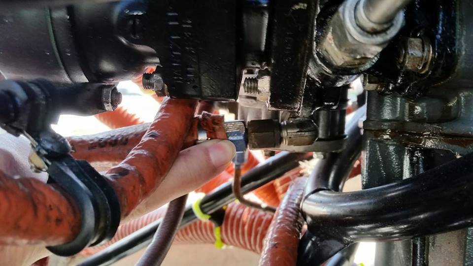
Now why would an engine stumble cause the fuel pressure to fluctuate?  That was yet another part of the puzzle.  We started pulling on the fuel lines.  If they were old and really stiff, they may have a crack in them that was aggravated when the engine stumbled and wobbled.  The fuel lines are covered in a heat resistant orange wrap that helps protect them from heat and vibration.  As the mechanic squeezed at them, he tugged and shook them.

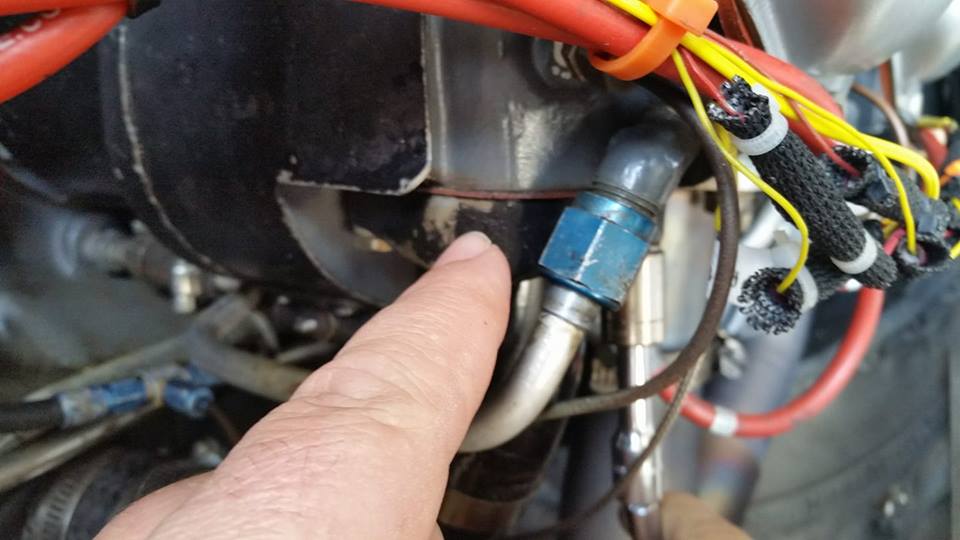
Then he spotted the problem.  The return line on the engine driven pump was loose.  The fitting had come loose and backed off the nut a couple of turns. It was just enough to allow some air to be sucked into the system when under pressure.

A couple of turns with a wrench and the fitting was seated tightly and no amount of shaking the hose would make it come loose.   Did we just find the problem?  The mechanic and I were hopeful.  Now it was time for a run-up of the plane to check the fuel pressure readings at the gauge.

Success!  The fuel pressure was now stable and right at the top of the arc.   A good suggestion from another mechanic was to paint some torque seal across the fittings.  Then it becomes easy during visual inspection to see if a fitting has slipped. A simple problem to fix, but not so simple to find.

Sunny Side Up Gets Dual Exhaust

In November of 2017 my wife’s grandmother passed away.  So we had to make last minute travel arrangements or take the Comanche to Staten Island New York.  We opted to fly ourselves.   On the trip up it became chillingly clear that the heater was dumping deadly carbon monoxide into our cockpit.  We had to fly in a very cold airplane all the way up and back.    My wife made it very clear that I was to fix this problem.

One option was to purchase the same system from one of many places that sells the standard parts.  This option had merits of price and ease of replacement.  The downside was I might be right back in the same situation too soon.  There are also Airworthiness Directives (ADs) on the exhaust for failed baffling inside the muffler.  The pipes also have a tendency to crack right by the muffler because of vibration.

Instead I opted for a dual exhaust system which eliminated several problems with the old one. The dual exhaust is an STC’d option from Aviation Performance Products.  They offered a stainless steel dual exhaust option.

Pic of the exhaust system

180 exhaust system

180 exhaust system

The product took a week from order to delivery.  I picked up the product from the Melbourne shop and took the kit to my mechanic.

The Entire Dual exhaust kit

The Entire Dual exhaust kit

My mechanic and I spoke at length about the install process and what would need to be done.  A couple of items came up. I had to order new exhaust gaskets as the kit does not come with them.   Also all the SCAT hose would need to be replaced with all new lengths and whole new runs of hose.  Also I would need to make considerable modifications to my cowling, including cutting away some on the bottom edge to allow the new dual pipes to be low enough below the plane’s belly and not contact the cowling itself.  Also I would need to add new air intake ports for the fresh air vents.  Lastly I needed an adapter for the left side heat muff so that the 2 inch intake port from the back of the engine baffles would fit on the 3 inch port on the heat muff.

With all the pieces figured out the installation began.  We took off the cowling and took stock of the old exhaust system

Old Exhaust Right Side

Old Exhaust Right Side

The old exhaust system is big and bulky the pipes cross over underneath and then go to the back of the engine and include a giant muffler, which takes up the entire back of the compartment from the engine to the firewall.   The heat muff for the carburetor heat was held on by ten screws and nuts and I had to seal it with high temperature RTV so that it worked sufficiently.

Old Exhaust Left Side

Old Exhaust Left Side

The left side of the exhaust was much the same, I added a support to help with the vibration that often caused the exhaust to crack and fail right at the muffler on this side.  I was hopeful that all these problems would go away with the new installation.

We set to work removing the old exhaust and ended up with quite a collection of parts.

The Old Exhaust

The Old Exhaust

The old exhaust system was pretty easy to remove, but took a bit of coordination as we had to disconnect both sides before it could be removed.  With the exhaust removed it became clear just how much space that system used in the engine compartment.

Old Exhaust Removed

Old Exhaust Removed

With the old exhaust off we started the modifications to the fuel pump.  The new muffler comes very close to the pump.  So it had to be raised up with an extension plate so that it was further away from the heat of the exhaust pipe.

Modified Fuel Boost Pump

Modified Fuel Boost Pump

After we made a trial fit of the system, it was time to start the modifications on the bottom Cowl.  The plans come with some templates that can be cut out and placed upon the cowling.  from there you can make your own adjustments, as the template is only a rough guide and more modifications might be needed.

Template for Cowl Trim

Template for Cowl Trim

This modification was nerve wracking.  Take too much and we wreck the cowl.  Take too little and the mufflers don’t fit.  We had to do this process two or three times before we were sure it was right. On top of all this cutting we than had to make new doubler plates and rivet them on.  We originally intended to replace the fresh air intake ports on the bottom of the cowling with NACA ducts.  However this option would not work as the new mufflers were in the way.

Bottom Cowl Modification

Bottom Cowl Modification

As part of the STC old parts from the existing system were incorporated.  In order to provide fresh air, two new intake ports had to be added to the cowl.  These ports were to be cut off the muffler heat muff and attached to the front of the cowling on top of the airbox.

New Fresh Air Ports

New Fresh Air Ports

My Comanche has dual heat ports and dual fresh air ports on each side of the firewall.  New SCAT hose had to be run for both fresh air and heat.  The right side muffler handles the carburetor heat air.  So the air intake off the back of the baffle puts hot air into the carb box.  We also drilled out holes for the exhaust gas temperature (EGT) probes.  I decided to try them on the inside, so they were tucked out of the way. This worked okay on the right side, but we had to do something slightly different on the left.

Right Side of Dual Exhaust Installed

Right Side of Dual Exhaust Installed

The left side was a real challenge. The heat probes would not fit under the baffling  so they ended up more on the back of the pipes than on the inside our outside.  Also as the picture shows, we had to run many new lengths of SCAT tubing from the left muffler to all the heat ports.  Both the left and right heat and windshield defrost all come off this muffler.

Left Side Exhaust

Left Side Exhaust


A note on securing the SCAT tubing.  I did not use adel clamps.  My mechanic and I talked about how to secure them and we decided together that some zip ties would work.  I used some high temp clear plastic hose over the zip tie to prevent wearing and then a small piece of rubber tubing to create a stand off.  Now the pipe would be secure and protected against vibration wear.   Once these ties were tightened, they held the pipes in place.

Zip Tied Hoses

Zip Tied Hoses

There are several perks to this new exhaust.  The heat now works fantastically and no more carbon monoxide in the cabin.  The engine sounds different as the exhaust has a deeper more rumbling tone to it.  Also much less heat transfer from through the firewall making the dashboard hot. Overall this project was a good change.  I now have a much better exhaust system.  I am not yet sure if it was worth all the troubles, but it does work as advertised and does seem to improve the situation quite a bit.


Sunny Side Up – New Instrument Panel

Day 1

The worlds greatest Comanche 180 – Sunny Side Up is in the process of getting a new instrument panel. The original “Scatter dash” as we call it included some antiquated and slightly out of adjustment instruments. It was time for an upgrade.

The original panel

The original panel

Getting all the old instruments out was not too difficult. The attitude indicator and the directional gyro were enormous. These two instruments took up a good portion of the space behind the dashboard.

Starting to remove to old panel

Starting to remove to old panel

The old autopilot a Piper Autocontrol 2 was a marvel of mechanical engineering. Almost fully mechanical with a mix of simple electronics to make a wing leveler that will follow a heading bug. The problem was that it would occasionally malfunction and try to put me in a hard right turn which almost resulted in a wing over. It was time for this very old technology to go.

All the instruments out

All the instruments out

Cutting the original panel was a bit nerve wracking. Once the cutting wheel spun up and was put to the metal there was no going back. I was not committed to the change. Much planning went into the cutting to make sure we did it right.

Starting to cut the old panel

Starting to cut the old panel

Cutting the panel sprayed aluminum dust everywhere. What a mess it made. Following the directions in the STC paperwork, we cut away every bit required. I was aware we would have to tweak, but just not how much more lay in store.

All the old panel cut away

All the old panel cut away

Setting the new panels in place to check the fit gave me a false sense of completion. I began to get hopeful and think that there was not much left to do. That was a bad way to think as there were many slow and tedious tasks ahead.

Checking the fit of the new panel

Checking the fit of the new panel

Day 2

Today was a day of little visible progress although much was done.

The fine tuning of the fit of the panel was done. This required a lot of re-trimming of the cut areas and tweaking some drill points. Once we got that all set, we had to drill several holes in the new panel and into the meat of the remaining frame. Then countersinking every hole and confirming fit.

One of the unforeseen issues is that there is no standard design for all the plumbing behind the instruments. The Comanche had a “scatter panel” until near the end of production and we are putting in instruments that were never in the plane before so we have to kind of make it up as we go. Well not entirely, we have looked at later models and are trying to mimic that plumbing as best we can and apply some common sense.

Checking the instructions, measuring the panel again and designing the plumbing for all the instruments.

Checking the instructions, measuring the panel again and designing the plumbing for all the instruments.

Hours went into confirming the alignment of every screw hole. Notice the vacuum filter in the picture above? No such thing ever existed on this plane. Nope none. Had to make up our own plumbing to add it in as the new DG and AI require one.

Painted the panel a classic flat black.

Painted the panel a classic flat black.


Day 3

More work on the panel today.
I spent three hours getting the right side panel finished up. There were lots of little details to get exactly right. Getting some of the screws into the ELT was an exercise in contortion. Those little holes were way up in the corner and reaching them was a challenge.

Right side is in

Right side is in

The two smaller holes are for some future updates.

The next biggest time suck was the breaker panel. Moving the breakers from underneath the panel, to the right side took a lot of concentration. Each breaker had to be removed individually from the bottom bus bar, rotated 180 degrees and then all the wires reattached and a new bus bar installed. Of course, there were those mystery wires the went to nowhere and a couple of the breakers were completely empty. Woof!

The breaker panel.

The breaker panel.

Left and right panel installed

Left and right panel installed

Already tired, we finished up for the night by securing the left panel in place. The fit and finish was good, but it still needs a bit of trimming.

The next three steps
1. Secure all the wires behind the panel
2. Install the pitot system gages
3. Install the vacuum system

Day 4

Progress is measured in hours and inches right now. So many little tasks each requiring many small steps to achieve.

For example, We have this wire – not sure what it does. It has a 15 amp fuse that was blown plugged into it. Not sure how long it has been blown or what it does. Tracing it out has been a challenge.

I spent the better part of 6 hours running all the plumbing for the gauges. The airspeed is connected to the altimeter, the altimeter is connected to the VSI. The airspeed also has the ram air from the pitot tube and the VSI is connected to the static port all the way in the tail of the plane.
As I shared earlier the plumbing for the vacuum gauges was all new too. Each and every pipe and connection was new.

An interesting solution for the empty holes. The manufacturer sent all the holes cut from the panel. I took some strips of 40 gauge aluminum and made some strips long enough to go across the holes diagonally. Then I drilled and tapped them and secured them across the holes with #6 screws. Then I applied a glop of silicone and pressed the blank into the hole I then taped them in place to secure them until the silicone cures.

Tomorrow we have some final items to complete.

  • attach power to the EDM700
  • find the wire for the pitot heat (F2C)
  • test all the circuits
  • swing the gear
  • install all the panel labels
  • test the vacuum system
  • test the pitot system

Day 5

Attaching the EDM700

We put the panel all back together and started testing.  Some initial issues were the EDM700 kept reporting low voltage.  We tried lots of things, and finally solved it by cleaning and adjusting the bus bar that connected the circuit breaker.  Seems there was some film on the metal that was creating resistance and reducing voltage to the unit.

Finding the Pitot Heat Wire

Chasing the pitot heat wire has proven an exercise in futility.  Even with a wire chaser, we were unable to find the end of the wire in the cabin.  It seems we are going to have to run a new wire from the cabin, through the wing and out to the pitot tube heating element

Test all the Circuits

The gauges were also an issue.  The amp meter read a constant discharge.  A test with another amp meter showed no such thing.  With a bit of adjustment we were able to get proper reading.  All the instrument gauges read slightly differently and I thought maybe it was a grounding issue.  I ran a new ground cable and it seemed to make it better, but not exactly the same as it was before.


Swing the Gear

One of the most important test we did, at least for my peace of mind, was a gear swing.  My reasoning was that we moved and touched every single wire that connected the switches and lights that controlled the gear.  I wanted t make sure it was all working properly.  I am glad we did.  The gear lights did not work and had to be replaced.

Test the Vacuum System

This was pretty easy.  We pulled the plane out of the hangar and started it up.  Within a few seconds the instruments began to spin up and I heard what can only be described as “kissy noises” coming from the panel.  I felt around behind each instrument and found the loose connections and tightened the hose clamps a bit more to make them stay stable.

After many more hours we arrived at a functional product.  Sure there are still a few things to do, including touching up my scrape at the top of the airspeed indicator and adding all the labels.  For now it is looking good and then final touches will happen over the next few weeks.

The Finished Panel


I hit a bird

Turkey Vulture vs Comanche

The particulars:

  • N8244P: 1964 Comanche 180.
  • TTAF: ~3200
  • SMOH ~900
  • STOH ~60

comanche-at-dons-shopI was descending out of 4000 about 12 miles south of KOCF, setting up for the ILS 36 approach, when a big black turkey vulture dove into my path and I chopped it up with the prop. Blood and guts everywhere. The right wing suffered some minor damage from the chunks hitting the leading edge. I think the worst part was when I realized I could not avoid the bird. I had just a split second to yank the yoke to the left and the bird hit the prop at about the 2 o’clock position. I think that saved me as the prop chewed it up and threw most of it down and to the right, away from the cockpit. The insurance company wants a tear down and inspection. The craft is now with my trusted mechanic Don and getting a tear down and inspection.

I guess the silver lining is that I did not die. Things could have gone way worse on this one. I was at 24 square in a descent at about 160 kts. That bird could have blasted through my windshield and disabled me with a much worse outcome.   Another silver lining, and perhaps the best one, is that a mechanic I really trust is doing the repairs. Some days I think someone is looking out for me. I have done so many foolish things that I should have long ago won a Darwin award. Yet here I am.

Converting to a Major Overhaul

I was really worried that my stabilator was damaged but none found. After a few conversations with Don, I am going to pay the extra and turn this into a major overhaul.  The prop is going out for inspection and repair, possibly overhaul. I will have to ask Don which is happening. It has maybe 100 hours on it. There was no visible damage I could see but always better safe than sorry.

Engine parts OK – somewhat

The engine is all apart. The good news is that the bottom end of the engine, factory new in 1975 ish, containing the crank and cam all looks good. The top end, which was recently overhauled – the cylinders, pistons, and rods etc, seems to be less than stellar workmanship.

AD needs to be done

While Don was tearing through the engine he also looked at the logs and discovered an AD – Airworthiness Directive that had not been done.

DATE: January 30, 2003 Service Bulletin No. 475C
(Supersedes Service Bulletin No. 475B)
Engineering Aspects are
FAA Approved
SUBJECT: Crankshaft Gear Modification and Assembly Procedures
MODELS AFFECTED: All Lycoming direct drive piston aircraft engines (including VO-360 and
IVO-360; excepting O-320-H, O-360-E, LO-360-E, TO-360-E, LTO-360-E,
and TIO-541 series engines).
TIME OF COMPLIANCE: During overhaul, after a propeller strike, or whenever crankshaft gear removal is required.

The infamous gear now in compliance with the scalloped edges.  As explained by my Mechanic “This pic is of the infamous AD crank gear. You will see the scalloped flange. It used to be solid round. The idea of the AD is so you can confirm that the gear is flush and tight on the crank by being able to slip a feeler gauge into the scalloped area to confirm it is flush with the end of the crank...”

AD complied

AD complied


New Crank or Not?

inspected-camMr. Don, my mechanic and I have been discussing reusing my existing cam and buying a new one. The plan was to buy a new one and if my existing came back with a yellow tag, we would sell it on eBay for someone looking for a used cam.  Don had a conversation with the shop that did my existing cam shaft and the shop owner stated that the failure rate is negligible between new and resurfaced cams.  The final point that was the clincher that made me decide to use the existing cam was that my existing cam is tried and true – we know it is good it already ran 900 hours without issue. Odds are that it will continue to perform just a good as a new one. In fact because it has already been stressed and found to sustain – it is just as likely to last as a new one.

Reassembly

The process of putting the engine back together was slow and careful.  Each part after thorough inspection was then carefully put back into the engine case and properly fitted.  The assembly took a couple of days and then installing the engine on the plane a few more days.  This is not a process to be rushed.

comanche-engine-on


Pulling the Dent

A chunk of the bird hit the leading edge of the right wing. leaving a golf ball sized dent.   The mechanic used a drill and dent puller to pull the dent back out.  Then some body filler and paint to smooth it out.  he also repainted the leading edge so it was pretty much invisible.

Before:

before-dent


After:

repaired-dent


Plane all back together 1/1/2016

After three months of waiting, the plane is back together and looking good.   The engine is running great and the dent is gone.  Hopefully no more issues for a while.

sunny-side-up-hangared